 Structa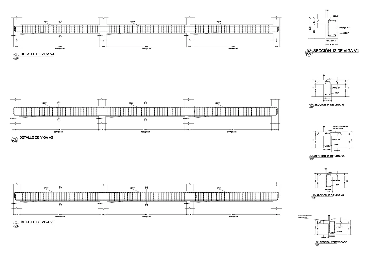
Reinforcement
Beam detailing from ETABS: where to start
Prepare the model, bring in the reinforcement information and review your beam details.
Read the guideTHE STRUCTACAD BLOG
IDEAS FOR YOUR NEXT DRAWING SETPractical guides for the space between your structural model and the drawings you deliver.
THE ESSENTIAL GUIDE
Make more of the model you already have. A practical workflow for turning geometry, reinforcement and quantities into editable CAD drawings.
Read the guide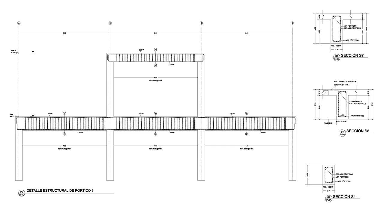
THE KNOWLEDGE LIBRARY
Pick a topic. Find a workflow you can put to work.
Reinforcement
Prepare the model, bring in the reinforcement information and review your beam details.
Read the guide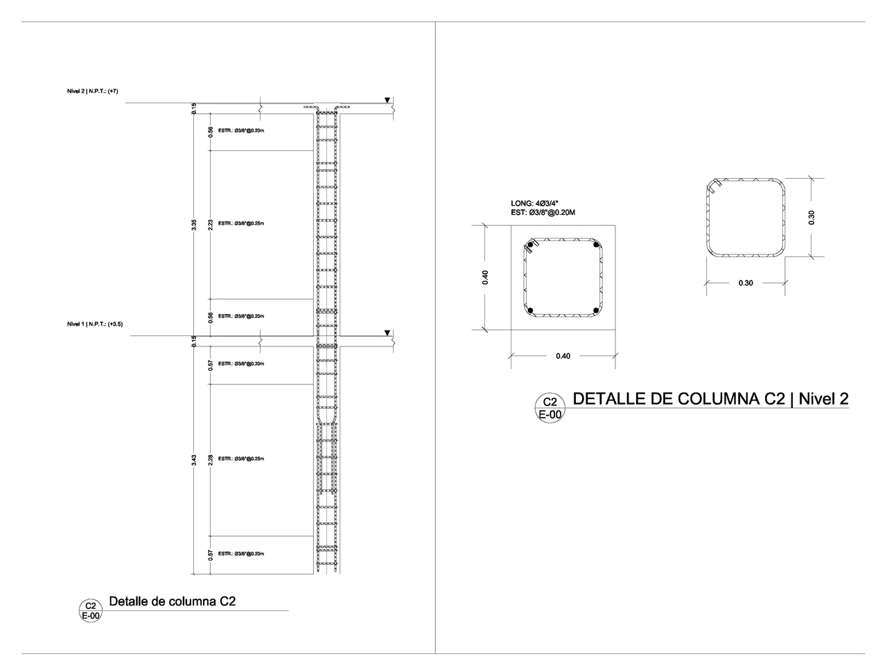
Reinforcement
Keep column sections, levels and reinforcement clear throughout the drawing set.
Read the guide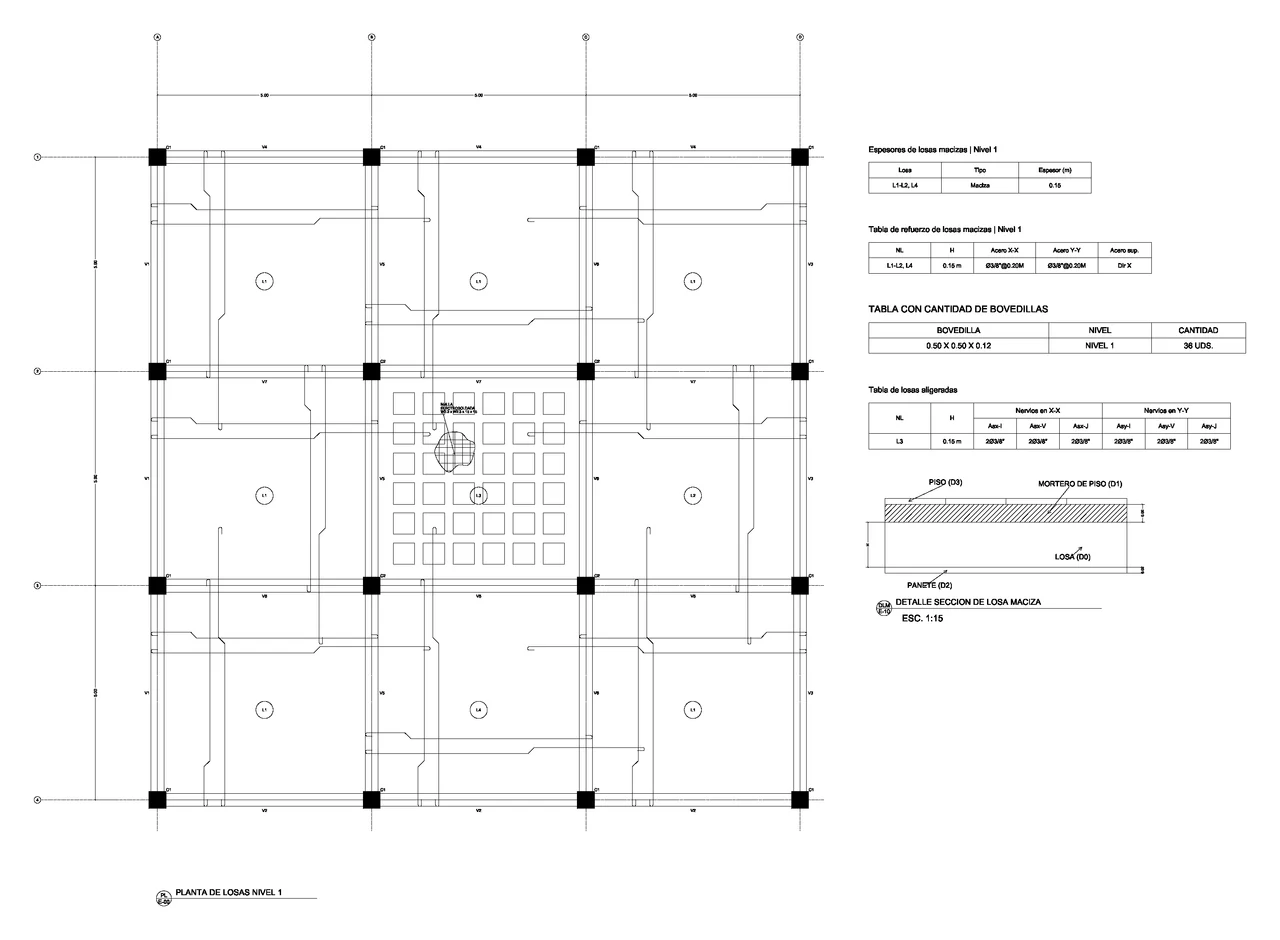
Drawings
What drawing automation can do, and what to check before you export.
Read the guideETABS to CAD
Choose an editable exchange format and finish the drawing in your CAD workflow.
Read the guide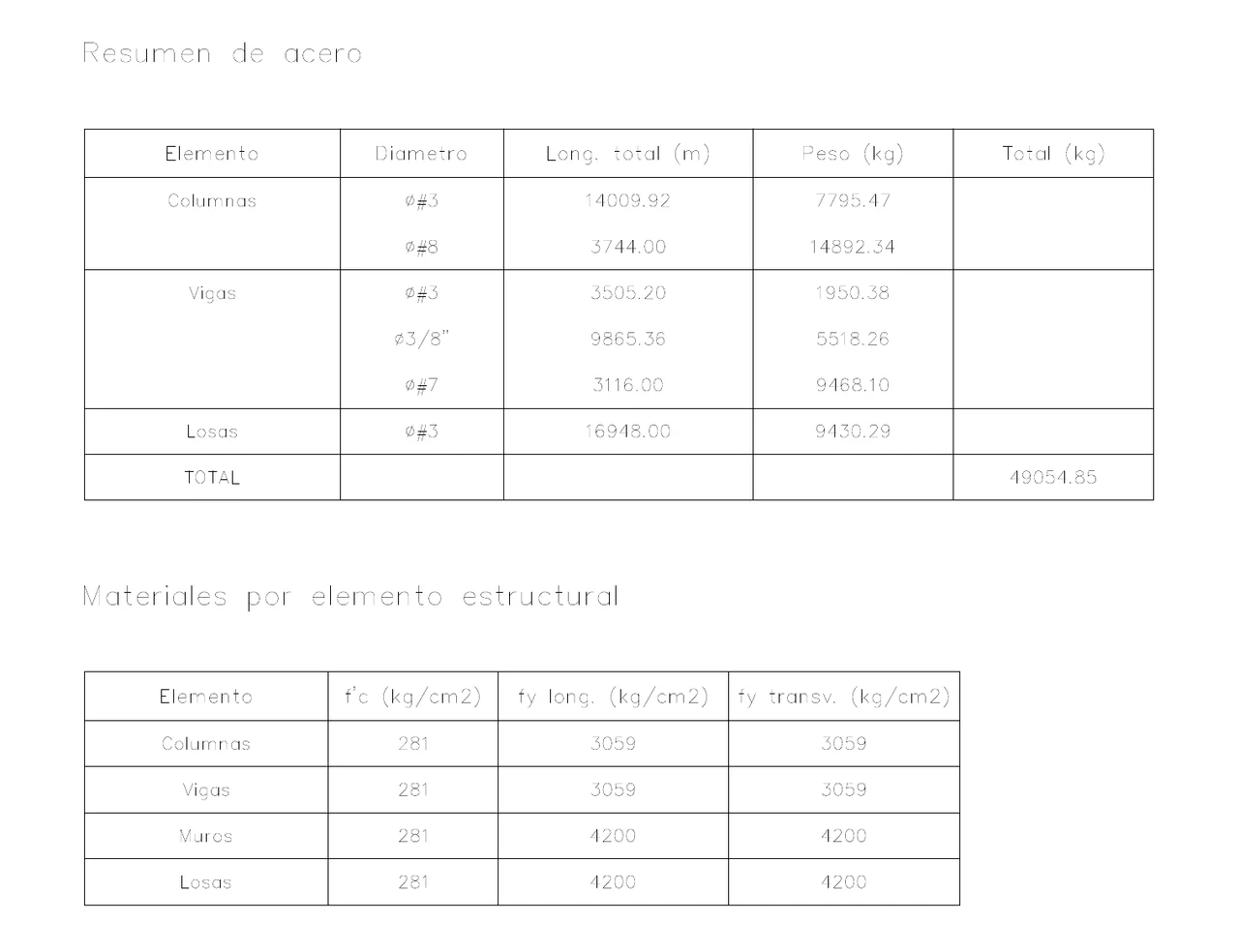
Quantities
Check concrete and reinforcement quantities before using them in an estimate.
Read the guide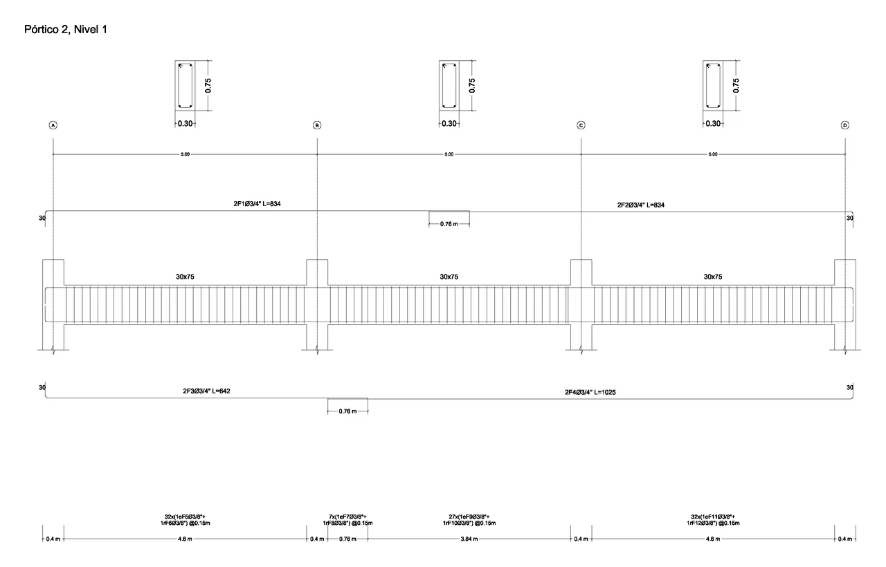
Midas Gen
Bring model information into a practical workflow for editable AutoCAD drawings.
Read the guideTry a broader term, such as beams or DXF, or clear the filters.
THE WORKFLOW, EXPLAINED
How to turn structural model information into a first-pass drawing set, then review and refine it in CAD.
A concrete building model may already contain the information the drafting team needs: levels, grids, beams, columns, walls, slabs, openings, and element relationships. Even so, the documentation phase often starts again in CAD.
Engineers and drafters still need to prepare floor plans, trace structural elements, place labels, draw frame views, create beam and column details, organize dimensions, and produce a file that can be reviewed by the team. That work is necessary, but much of it is repetitive.
The goal of a drafting automation process is not to remove review. The goal is to reduce the blank-page work that happens before review can even begin.
StructaCAD is built around a practical drafting sequence:
structural model -> first-pass drawings -> editable DXF -> CAD review and cleanup.
The user can model directly or work from imported structural information, generate a drawing package, then continue the final presentation and checking process in AutoCAD or another CAD-compatible process.
This matters because most offices already have CAD standards, preferred layers, text styles, title blocks, and review habits. A useful automation tool should fit into that process instead of forcing everyone into a closed system.
Bring the ETABS geometry and the available concrete design results into StructaCAD. Check that your import includes the required beam steel areas; geometry alone is not a substitute for design results. The reinforcement information is associated with the relevant beams, spans and stations to help prepare top and bottom reinforcement.
Using that demand as the starting point, StructaCAD proposes practical reinforcement for beam and frame details. The goal is to satisfy required steel area, minimum reinforcement ratio, minimum bar spacing, maximum bar diameter, and constructible detailing rules.
StructaCAD also helps generate slab plan drawings from the structural model. The output can show slab panels, labels, thicknesses, main reinforcement direction, and reinforcement information according to the slab system.
For solid slabs, the program organizes bottom mid-panel reinforcement, top reinforcement over supports, and additional reinforcement where needed. For ribbed or one-way slab systems, it keeps the plan readable while leaving the DXF ready for review and adjustment in AutoCAD.
When the model comes from ETABS, not every wall should be treated the same in drawings or quantities. StructaCAD lets users classify imported walls as structural concrete walls, masonry walls, or non-bearing walls.
This classification helps each wall receive the right treatment in documentation: concrete walls can be part of the structural system and details, masonry walls can be separated for takeoff and estimating, and non-bearing walls can remain identified without being confused with primary resisting elements.
A useful reinforced concrete DXF export should provide more than a single plan view. The package should give the user enough structured drafting output to start reviewing immediately.
The output should be treated as a drafting baseline. It should save time by placing the repetitive information, while still leaving space for engineering judgment, office standards, and project-specific corrections.
DXF keeps the process flexible. Engineers and drafters can open the generated file in AutoCAD or CAD-compatible software, inspect the geometry, adjust layers, modify annotations, and continue the drawing process using their normal standards.
That flexibility is important because structural drawings are not only technical outputs. They also depend on local conventions, office standards, client expectations, code notes, sheet layout, and presentation style.
A first-pass DXF export is valuable when it reduces repetitive drafting while still remaining editable and reviewable.
StructaCAD is especially relevant for users who already work around reinforced concrete documentation and want a lighter way to get from model information to CAD output.
StructaCAD does not replace a qualified structural engineer, professional judgment, code checks, detailing decisions, or project-specific review.
The generated drawings should be checked for geometry, scale, reinforcement assumptions, member labels, dimensions, constructability, local requirements, and office standards before being used as part of a real deliverable.
The safest way to think about StructaCAD is as a documentation accelerator: it helps generate a structured first draft, then the engineer or drafter reviews and refines it.
StructaCAD is being improved around real drafting needs: cleaner DXF exports, better element representation, more readable plans, better beam and column details, quantity outputs, and unit price analysis.
The long-term direction is a practical bridge between structural modeling and structural documentation:
model the structure -> generate drawings -> extract quantities -> prepare pricing -> export editable CAD deliverables.
FROM READING TO DOING
Try the workflow with a project you know. Generate your drawings, review the details and take them into CAD.
On your phone? Explore the guides here and continue with your model on your computer.